Introduction
In this project, I learn about sensor noise and fitering of data extracted from MPU6050.
In a way, this project is a continuation of an earlier one where I integrated an MPU6050 with an Arduino Uno.
In this project, I learn about sensor noise and fitering of data extracted from MPU6050.
In a way, this project is a continuation of an earlier one where I integrated an MPU6050 with an Arduino Uno.
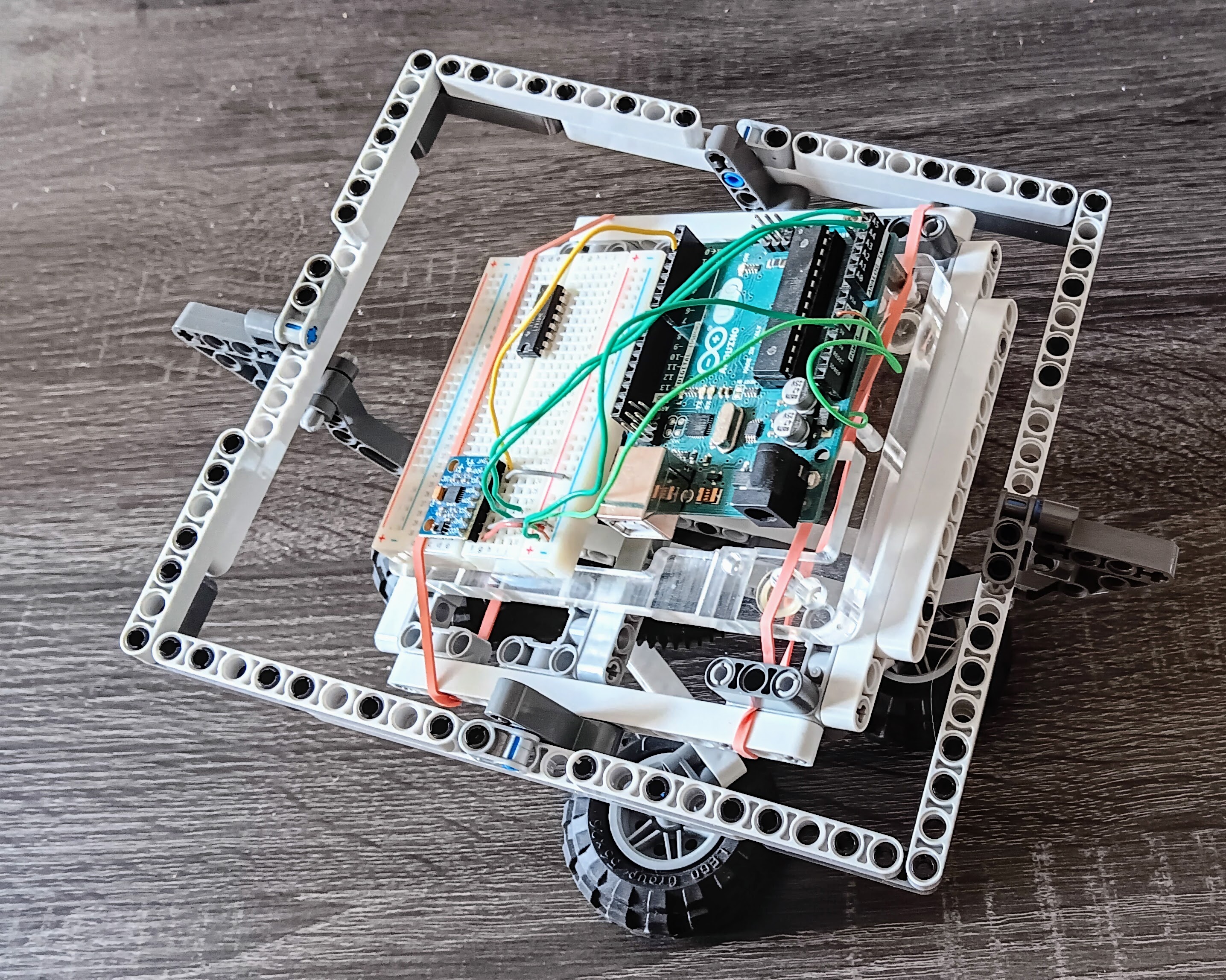
The experiment deserved a better gimbal for measuring the results of the experiment. Here's a picture of the second version, which provides 3-degrees of freedom.
The code that I wrote for the previous project gathered accelerometer and gyroscope data at the X-Y-Z axes.
In this project, I'm adding the capability to measure total amplitude of the data (instead of X-Y-Z axes), plus the standard deviation.
I then create a simple data logger to understand noise characteristics.
The loop in the Arduino code performs the following operations:
The data analysis in showResults reports the following information:
#include <Wire.h>

const int MPU_addr = 0x68;
int16_t AcX, AcY, AcZ, GyX, GyY, GyZ;

// Scaling factors
const float accel_scale = 16384.0;
const float gyro_scale = 131.0;

// Analysis variables
const int SAMPLE_SIZE = 50;
const int LOOP_DELAY = 50;  // in msec
const int BOARD_DELAY = 1000;  // in msec

int count = 0;
float sum_ax = 0, sum_ay = 0, sum_az = 0;
float sum_gx = 0, sum_gy = 0, sum_gz = 0;
float sum_amag = 0, sum_gmag = 0;
float sum_ax2 = 0, sum_ay2 = 0, sum_az2 = 0;
float sum_amag2 = 0, sum_gmag2 = 0;

void setup() {
  Serial.begin(9600);
  Wire.begin();

  // Wake up MPU
  Wire.beginTransmission(MPU_addr);
  Wire.write(0x6B);
  Wire.write(0);
  Wire.endTransmission(true);

  Serial.println("=== IMU Noise Test ===");
  Serial.println("Keep IMU still. Testing...");
  delay(BOARD_DELAY);  // wait for the board to be ready
}

void loop() {
  // Read IMU
  Wire.beginTransmission(MPU_addr);
  Wire.write(0x3B);
  Wire.endTransmission(false);
  Wire.requestFrom(MPU_addr, 14, true);

  AcX = Wire.read() << 8 | Wire.read();
  AcY = Wire.read() << 8 | Wire.read();
  AcZ = Wire.read() << 8 | Wire.read();
  Wire.read(); Wire.read(); // Skip temperature
  GyX = Wire.read() << 8 | Wire.read();
  GyY = Wire.read() << 8 | Wire.read();
  GyZ = Wire.read() << 8 | Wire.read();

  // Convert IMU data to physical units
  float ax = AcX / accel_scale;
  float ay = AcY / accel_scale;
  float az = AcZ / accel_scale;
  float gx = GyX / gyro_scale;
  float gy = GyY / gyro_scale;
  float gz = GyZ / gyro_scale;

  if (count < SAMPLE_SIZE) {
    /* We're going to analyze the data for every SAMPLE_SIZE samples.
       This here code accumulates the data that's received from the IMU
       and when the correct number of samples has been received, then
       then next loop runs the code in ELSE section, which prints the
       results of the analysis.
    */
    // Calculate magnitudes of accelerometer and gyroscope x-y-z- data
    float amag = sqrt(ax*ax + ay*ay + az*az);
    float gmag = sqrt(gx*gx + gy*gy + gz*gz);

    // Accumulate sums for mean
    sum_ax += ax; sum_ay += ay; sum_az += az;
    sum_gx += gx; sum_gy += gy; sum_gz += gz;
    sum_amag += amag; sum_gmag += gmag;

    // Accumulate sums of squares for std dev
    sum_ax2 += ax*ax; sum_ay2 += ay*ay; sum_az2 += az*az;
    sum_amag2 += amag*amag; sum_gmag2 += gmag*gmag;

    count++;

    if (count % 10 == 0) {
      Serial.print("Progress: ");
      Serial.print(count);
      Serial.print("/");
      Serial.println(SAMPLE_SIZE);
    }
  } else {
    // Calculate and display results
    showResults();

    // Reset for next test
    count = 0;
    sum_ax = sum_ay = sum_az = 0;
    sum_gx = sum_gy = sum_gz = 0;
    sum_amag = sum_gmag = 0;
    sum_ax2 = sum_ay2 = sum_az2 = 0;
    sum_amag2 = sum_gmag2 = 0;
  }

  delay(LOOP_DELAY);
}

void showResults() {
  Serial.println("\n=== NOISE ANALYSIS RESULTS ===");

  // Calculate means of data
  float avg_ax = sum_ax / SAMPLE_SIZE;
  float avg_ay = sum_ay / SAMPLE_SIZE;
  float avg_az = sum_az / SAMPLE_SIZE;
  float avg_amag = sum_amag / SAMPLE_SIZE;
  float avg_gmag = sum_gmag / SAMPLE_SIZE;

  // Calculate standard deviations using: sqrt((sum_x2 - n*mean^2)/(n-1))
  float std_ax = sqrt((sum_ax2 - SAMPLE_SIZE * avg_ax * avg_ax) / (SAMPLE_SIZE-1));
  float std_ay = sqrt((sum_ay2 - SAMPLE_SIZE * avg_ay * avg_ay) / (SAMPLE_SIZE-1));
  float std_az = sqrt((sum_az2 - SAMPLE_SIZE * avg_az * avg_az) / (SAMPLE_SIZE-1));
  float std_amag = sqrt((sum_amag2 - SAMPLE_SIZE * avg_amag * avg_amag) / (SAMPLE_SIZE-1));
  float std_gmag = sqrt((sum_gmag2 - SAMPLE_SIZE * avg_gmag * avg_gmag) / (SAMPLE_SIZE-1));
  float acc_err = abs(avg_amag-1.0);

  // Accelerometer results
  Serial.println("ACCELEROMETER:");
  Serial.print("X: "); Serial.print(avg_ax,3); Serial.print("g ±"); Serial.println(std_ax,4);
  Serial.print("Y: "); Serial.print(avg_ay,3); Serial.print("g ±"); Serial.println(std_ay,4);
  Serial.print("Z: "); Serial.print(avg_az,3); Serial.print("g ±"); Serial.println(std_az,4);
  Serial.print("Total: "); Serial.print(avg_amag,3); Serial.print("g ±"); Serial.print(std_amag,4);
  Serial.println(std_amag < 0.004 ? " [EXCELLENT]" : std_amag < 0.01 ? " [GOOD]" : " [POOR]");

  // Gyroscope results
  Serial.println("\nGYROSCOPE:");
  Serial.print("Total: "); Serial.print(avg_gmag,2); Serial.print("°/s ±"); Serial.print(std_gmag,3);
  Serial.println(std_gmag < 0.033 ? " [EXCELLENT]" : std_gmag < 0.05 ? " [GOOD]" : " [POOR]");

  // Health check
  Serial.println("\nGRAVITY CHECK:");
  Serial.print("Measurement Error: ");
  Serial.print(abs(avg_amag-1.0), 3);
  Serial.println(acc_err < 0.02 ? " [EXCELLENT]" : acc_err < 0.05 ? " [GOOD]" : " [POOR]");


  Serial.println("\nSPECS: Accel < 0.004g, Gyro < 0.033°/s\n");
}Results when X, Y, and Z = 0, and stationary
=== NOISE ANALYSIS RESULTS ===
ACCELEROMETER:
X: -0.051g ±0.0030
Y: 0.043g ±0.0030
Z: 0.784g ±0.0043
Total: 0.787g ±0.0044 [GOOD]

GYROSCOPE:
Total: 0.81°/s ±0.156 [POOR]

GRAVITY CHECK:
Measurement Error: 0.213 [POOR]

SPECS: Accel < 0.004g, Gyro < 0.033°/s
Results with X = -30° and stationary:
=== NOISE ANALYSIS RESULTS ===
ACCELEROMETER:
X: 0.075g ±0.0032
Y: -0.446g ±0.0028
Z: 0.683g ±0.0046
Total: 0.819g ±0.0040 [GOOD]

GYROSCOPE:
Total: 0.84°/s ±0.122 [POOR]

GRAVITY CHECK:
Measurement Error: 0.181 [POOR]

SPECS: Accel < 0.004g, Gyro < 0.033°/s
Results with Y = -30° and stationary:
=== NOISE ANALYSIS RESULTS ===
ACCELEROMETER:
X: -0.397g ±0.0041
Y: 0.040g ±0.0032
Z: 0.686g ±0.0045
Total: 0.793g ±0.0046 [GOOD]

GYROSCOPE:
Total: 0.81°/s ±0.112 [POOR]

GRAVITY CHECK:
Measurement Error: 0.207 [POOR]

SPECS: Accel < 0.004g, Gyro < 0.033°/sI made some minor adjustments to the code in showResults so I could plot the data using the Serial Plotter of the Arduino IDE. I turned on the Serial Plotter to see what happens to the data at different orientations:
But first, the code that used:
/* print these to use the Serial Plotter */
Serial.print(avg_amag); Serial.print(", ");
Serial.print(std_gmag); Serial.print(", ");
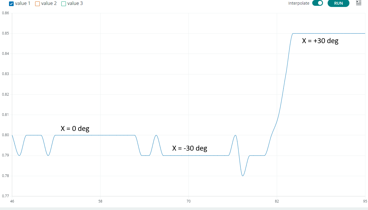
Serial.println(acc_err);Plot of the accelerometer data:
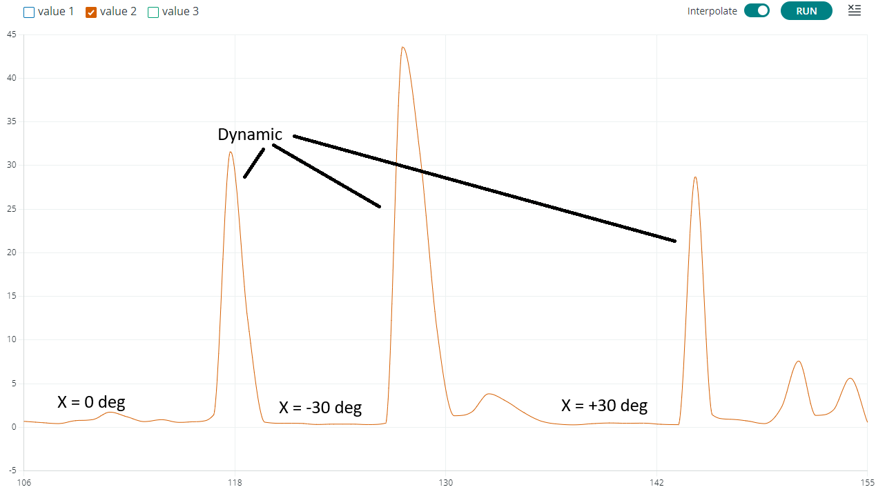
Plot of the gyroscope data:
Plot of error in measuring gravity:
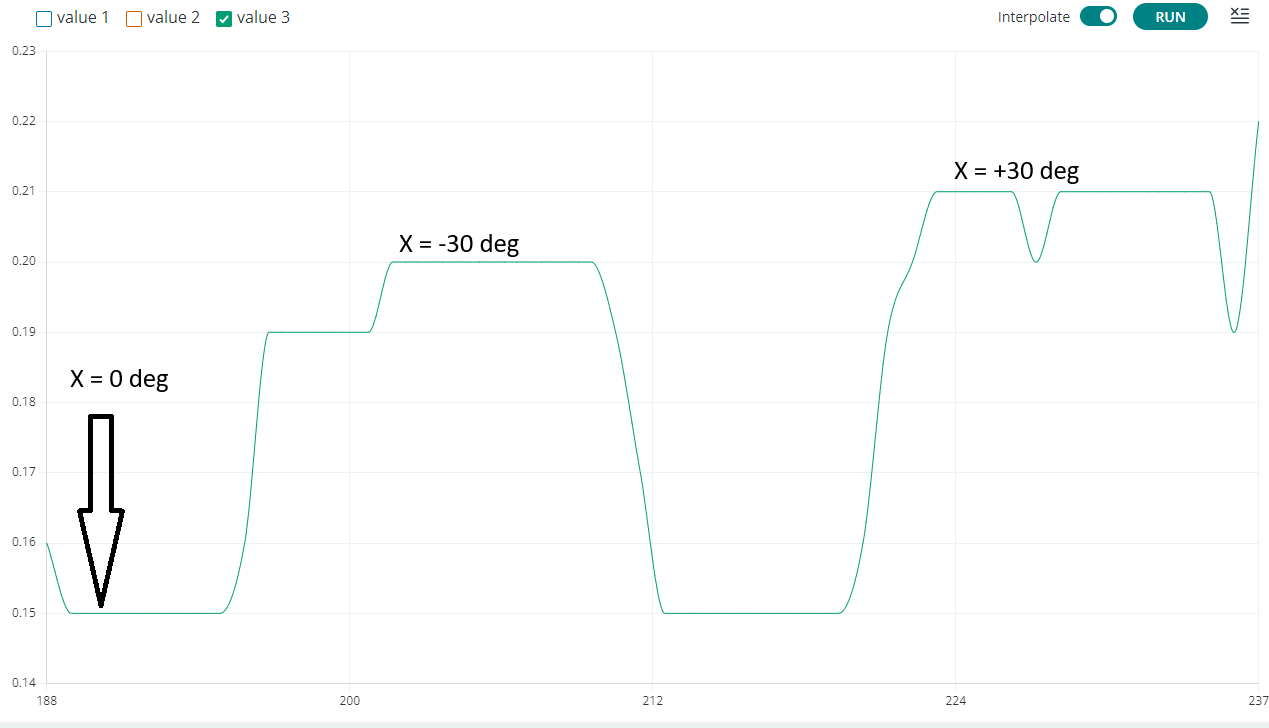
The plots confirm, as the printed observations, that:
The MPU6050's raw accelerometer and gyroscope data is inherently noisy, so filtering is essential for most applications. Here are the main filter types and their trade-offs:
#include <Wire.h>
#include <Adafruit_MPU6050.h>
#include <Adafruit_Sensor.h>

// Create an instance of the MPU6050 class called mpu
Adafruit_MPU6050 mpu;

// useful constants
const int SERIAL_BPS = 9600;
const int LOOP_DELAY = 10;

// Complementary filter variables
float dt = 0.01;  // Time step (10ms = 100Hz)
float alpha = 0.98;  // Filter coefficient (0.98 means 98% gyro, 2% accel)

// Angle estimates
float pitch = 0;
float roll = 0;

// Sensor event structures
sensors_event_t accel, gyro, temp;

// Values computed from sensor data in processRawData
float accel_pitch, accel_roll;
float gyro_pitch_rate, gyro_roll_rate;

// Timing
unsigned long last_time;

void setup() {
  Serial.begin(SERIAL_BPS);

  // Initialize MPU6050
  if (!mpu.begin()) {
    Serial.println("Failed to find MPU6050 chip");
    while (1) {
      delay(10);
    }
  }
  Serial.println("MPU6050 Found!");

  // Set accelerometer and gyroscope ranges
  mpu.setAccelerometerRange(MPU6050_RANGE_8_G);
  mpu.setGyroRange(MPU6050_RANGE_500_DEG);
  mpu.setFilterBandwidth(MPU6050_BAND_21_HZ);

  // Calibrate initial angles using accelerometer
  calibrateInitialAngles();

  last_time = millis();
}

void loop() {
  // Calculate time step
  unsigned long current_time = millis();
  dt = (current_time - last_time) / 1000.0;
  last_time = current_time;

  // Read sensor data
  mpu.getEvent(&accel, &gyro, &temp);

  // Process raw data
  processRawData();

  // Apply complementary filter
  complementaryFilter();

  // Print results
  printToPlot();

  delay(LOOP_DELAY);
}

void processRawData() {
  // Convert accelerometer values to angles (in degrees)
  // accel.acceleration values are in m/s²
  accel_pitch = atan2(accel.acceleration.y,
                     sqrt(accel.acceleration.x * accel.acceleration.x +
                          accel.acceleration.z * accel.acceleration.z)) * 180/PI;

  accel_roll = atan2(-accel.acceleration.x,
                    sqrt(accel.acceleration.y * accel.acceleration.y +
                         accel.acceleration.z * accel.acceleration.z)) * 180/PI;

  // Gyroscope values are in rad/s, convert to degrees/s
  gyro_pitch_rate = gyro.gyro.x * 180/PI;
  gyro_roll_rate = gyro.gyro.y * 180/PI;
}

void complementaryFilter() {
  // Complementary filter equation:
  // angle = alpha * (angle + gyro_rate * dt) + (1 - alpha) * accel_angle

  pitch = alpha * (pitch + gyro_pitch_rate * dt) + (1 - alpha) * accel_pitch;
  roll = alpha * (roll + gyro_roll_rate * dt) + (1 - alpha) * accel_roll;
}

void calibrateInitialAngles() {
  Serial.println("Calibrating... Keep sensor still");

  float sum_ax = 0, sum_ay = 0, sum_az = 0;
  int samples = 100;

  for (int i = 0; i < samples; i++) {
    mpu.getEvent(&accel, &gyro, &temp);
    sum_ax += accel.acceleration.x;
    sum_ay += accel.acceleration.y;
    sum_az += accel.acceleration.z;
    delay(20);
  }

  // Calculate average and initial angles
  float avg_ax = sum_ax / samples;
  float avg_ay = sum_ay / samples;
  float avg_az = sum_az / samples;

  pitch = atan2(avg_ay, sqrt(avg_ax*avg_ax + avg_az*avg_az)) * 180/PI;
  roll = atan2(-avg_ax, sqrt(avg_ay*avg_ay + avg_az*avg_az)) * 180/PI;

  Serial.println("Calibration complete");
}

void printResults() {
  // use this one instead of printToPlot if you plan to print the data
  // make sure to update the call in loop()
  Serial.print("Pitch: ");
  Serial.print(pitch, 2);
  Serial.print("°\tRoll: ");
  Serial.print(roll, 2);
  Serial.print("°\t");
  Serial.print("Accel P: ");
  Serial.print(accel_pitch, 2);
  Serial.print("°\tAccel R: ");
  Serial.print(accel_roll, 2);
  Serial.println("°");
}

void printToPlot() {
  // use this one instead of printResult if you plan to plot the data
  // make sure to update the call in loop()
  Serial.print(pitch, 2); Serial.print(", ");
  Serial.print(roll, 2); Serial.print(", ");
  Serial.print(accel_pitch, 2); Serial.print(", ");
  Serial.println(accel_roll, 2);
}

// Alternative implementation with adjustable parameters
void setFilterParameters(float new_alpha, float new_dt) {
  alpha = constrain(new_alpha, 0.0, 1.0);
  dt = new_dt;
}

// Function to get current angle estimates
float getPitch() {
  return pitch;
}

float getRoll() {
  return roll;
}The above code yields a graph similar to the following:
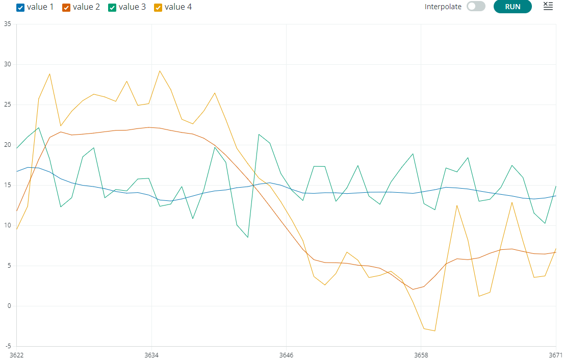
Where:
pitch value computed by the complementary filterroll value computed by the complementary filter.accel_pitch value computed directly from sensor accelerometer dataaccel_roll value computed dorectly from sensor accelerometer dataI was planning to display multiple grapes to demonstrate the effects of using different values of alpha. But then, the test platform (gimbal) is manual and I cannot adequately reproduce the results. Thus, I updated the code to compare the results through a statistical analysis of the effects of alpha.
| Alpha | P Std Dev | R Std Dev | P Noise | R Noise |
|---|---|---|---|---|
| 0.75 | 0.07 | 0.04 | 0.021 | 0.017 |
| 0.85 | 0.07 | 0.05 | 0.014 | 0.012 |
| 0.95 | 0.06 | 0.04 | 0.005 | 0.004 |
| 0.98 | nan | 0.03 | 0.002 | 0.001 |
| Alpha | P Std Dev | R Std Dev | P Noise | R Noise |
|---|---|---|---|---|
| 0.75 | 31.42 | 1.90 | 1.282 | 0.466 |
| 0.85 | 30.63 | 1.72 | 0.936 | 0.226 |
| 0.95 | 28.86 | 1.63 | 0.792 | 0.116 |
| 0.98 | 27.22 | 1.28 | 0.734 | 0.084 |